
FILES TO FINISHED PROJECT / MAKER GUIDE
How to make a layered topographic map with a laser cutter
A layered topographic map turns elevation contours into a physical stack. Plan the finished size, number of sheets and alignment before exporting, so the landscape works at the scale you want to make.
These are file-preparation and assembly planning instructions. The examples are generated artwork, not photographs of a completed physical test. Machine settings and material suitability need testing on your own equipment.
1. Choose a landscape and a relief workflow
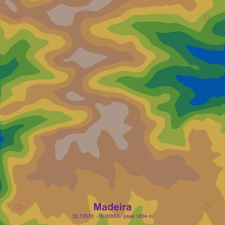
Open the free terrain studio, find a mountain, island or canyon, and preview a manageable area. Choose stacked layers for a physical sheet-by-sheet model. Contour-line, heightmap and shaded-relief modes serve different workflows; see the terrain file breakdown before generating.
Elevation data describes the landscape, not individual buildings or underwater depths. Look for ridges and valleys that remain distinct at your intended finished width.
2. Balance contour count and material thickness
The studio supports 2–20 contour layers or a real-world elevation interval of 5–500 meters. More levels can describe a slope more gradually, but also mean more cutting and assembly. Small contour islands may become fragile at a narrow finished size.
A useful planning estimate is sheet count × actual sheet thickness. Twelve full-height levels in 3 mm material make a maximum nominal stack of 36 mm before glue and backing. Six levels in 6 mm material also total 36 mm, but describe the slope in larger steps. Inspect the actual exported geometry; not every point in the landscape contains every level.
The contour interval describes real-world elevation. It is not the thickness you enter into a laser profile, and it does not automatically make the relief vertically true to scale.
3. Export and keep the assembly elements together
Enable the backing piece, registration guide and assembly frame if they suit your stacked project. After generation, extract the ZIP and read the supplied notes. Keep the numbered elevation SVGs, optional assembly elements and design settings together.
Review detached islands before cutting. A registration guide helps positioning; it does not turn loose pieces into a self-supporting structure. Plan a backing or temporary positioning method where the design needs one.
4. Prepare the contour SVGs in LightBurn
Import the SVG artwork into your laser software and verify the common finished dimensions. Do not resize individual height layers independently: they must keep the same map scale and alignment. Compare the combined artwork with the individual files before arranging sheets for cutting.
Assign the intended cut or engrave operation explicitly. Preview all paths, check narrow necks between contour regions, and account for the usable bed area. Our laser-cutting preparation guide also covers questions to ask an independent provider.
5. Make a small contour test
Use a representative section with tight turns and a small isolated island. Test the actual material thickness and machine setup you intend to use. Inspect both the cut edge and the strength of the pieces when you lift them from the bed.
Laser speed, power, passes and kerf compensation depend on your equipment and stock. Use supplier and machine guidance as the starting point; this digital sample is not a universal cutting profile.
6. Stack from low elevation to high
Label the sheets and dry-fit them in their numbered elevation order on a flat backing. Use the supplied guides or frame where appropriate, checking multiple landmarks rather than a single edge. Place detached islands before the next layer makes them difficult to reach.
Sand or colour surfaces when they are still accessible. Apply suitable adhesive sparingly, keep the assembly flat and allow it to cure according to the adhesive instructions. Check the final stack for shifted contours before framing.
When you need a different file type
Stacked terrain is a contour SVG workflow. A grayscale heightmap needs separate relief or CAM software before machining; it is not ready-to-run machine code. For printable models of buildings, use 3D city map STL and OBJ downloads. The terrain studio does not directly export a terrain STL.
Check these before committing to a full project
- All imported files share the intended dimensions and alignment.
- Small pieces have adequate support and a clear assembly plan.
- Cut and engraving operations have been previewed in your machine software.
- A representative test works in your actual material.
- Attribution and design notes are kept with your project.
Continue with the layered street map guide to compare the other SVG workflow. Check credits and generation costs before creating finished files.
LightBurn reference
For software-specific controls, see the official artwork import guide, Line mode and Fill mode documentation. Review current instructions for your version and machine.